|
|
|
The indoor guiding lightA fresh batch of light emitting diodes lay waiting in my drawer. The weather was bad and new year coming up. In other words: it was time for a flashy experiment, and I settled for a guiding-light for use in dark corridors. Well! I was not in possession of a dark corridor, but instead of such one I had a couple of good ideas to try out. The year was 1992 and light-emitting diodes were still regarded a little special.I decided for a project running directly on the mains -- no transformer, but still a low power-consumption! 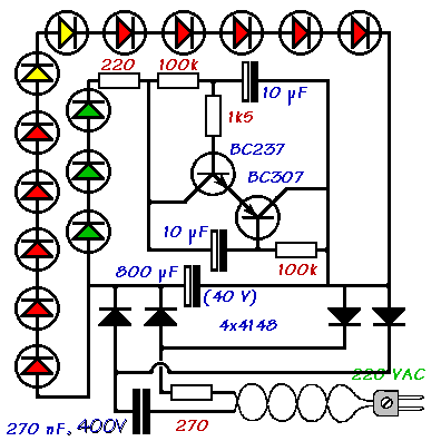 The circuit works like this: The AC from the mains is rectified and charges the 800 µF electrolytic capacitor, the voltage rising untill a current starts running through the red LEDs. These will kind of stabilise the voltage and prevent it from surpassing 18 Volts or so. The 270 nF capacitor in the mains input will limit the current to around 20 mA. The power consumption will not, due to phase-shifting, exceed 0.5 Watts! The circuit works like this: The AC from the mains is rectified and charges the 800 µF electrolytic capacitor, the voltage rising untill a current starts running through the red LEDs. These will kind of stabilise the voltage and prevent it from surpassing 18 Volts or so. The 270 nF capacitor in the mains input will limit the current to around 20 mA. The power consumption will not, due to phase-shifting, exceed 0.5 Watts!The two of the 10 µF capacitors will charge up too. When they reach about 8 V, the two transistors will start conducting and trig one another to swiftly enter a state of full conductivity. That will send a short cascade through the 220 Ohms and the green LEDs causing a short flash, during which the 10 µFs will discharge through the 1.5 kOhms and the transistor-bases, and make the circuit reenter the longer off-period. The device will work at 110 VAC as well, but the intensity of the light emitted by the red diodes will be reduced, whereas the green ones will flash at about the same rate and strength. |
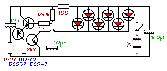 This circuit was battery-operated and made to fit into an old 'Marvi' bicycle-lamp. In 1992 LED rear lights were far from common and I was sometimes questioned about it in the street. A similar lamp running on the generator, was in fact stolen during a repair-session with a bicycle shop ('Tailor Cykler' in Copenhagen), the man insisting, that the lamp was broken so he 'threw it away'.